Wyliodrin STUDIO makes it easy to program and develop applications using a Raspberry Pi and a bunch of peripherals, such as LEDs, buttons and others. But not every user is able to purchase such devices, or maybe they want to test their code before running it, in order to be sure that no hardware components will be destroyed. For this problem, our team came up with a solution: the Raspberry Pi Simulator. This gives users the posibillity to simulate the output of a code running on a Raspberry Pi. Users are able to mirror the behaviour of LEDs turning on and off, buttons being pressed and 16x2 LCD screens. Currently, the simulator is quite restrictive one, allowing the use of only two JavaScript libraries. However, we are working hard to extend it to other languages and libraries.
The Simulator is really simple to use. You can choose between various predefined circuits. If you want to have a better control over the hardware part of your project, you can create your own schematic using Fritzing. In regard to software, the programming language currently supported is JavaScript, but we intend to include Python support as well.
In order to control the simulated hardware components, you can choose between two well-known libraries: onoff and lcd. You can find documentation about these libraries in the tutorial on How to use WyliodrinSTUDIO Simulator. To accees it, from within Wyliodrin STUDIO, just click the Question Mark button on the right side of the Raspberry Pi Simulator tab, right under the tab list.
Now, let's see a description on how to use the Wyliodrin STUDIO Raspberry Pi Simulator, and what you can do with it!
Connecting to the Raspberry Pi Simulator
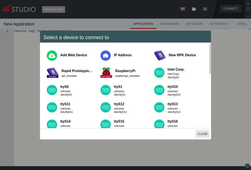
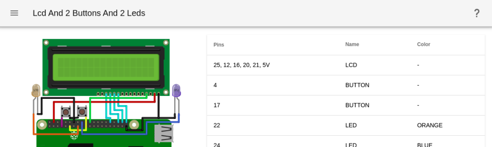
After you open Wyliodrin STUDIO, you have to connect to one of the simulators available in the Connection window. Once connected, you will notice a new tab, which is named RASPBERRY PI SIMULATOR. If you click it, you will see a circuit (further on, we call the circuit, a schematic) already loaded, next to a table displaying the connections between the components.
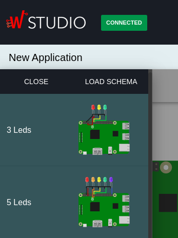
There are a few predefined circuits available. You can select the circuit by clicking on the menu button on the left side of the circuit's name. For now, you can choose between Raspberry Pis connected to LEDs, buttons and 16x2 LCD screens. You can create your own circuits using Fritzing. For now, there is a limited subset of components that Wyliodrin STUDIO can emulate, but we are working on supporting more.
Using Fritzing to create your own circuit
Now, let's show you how to create your own circuits.
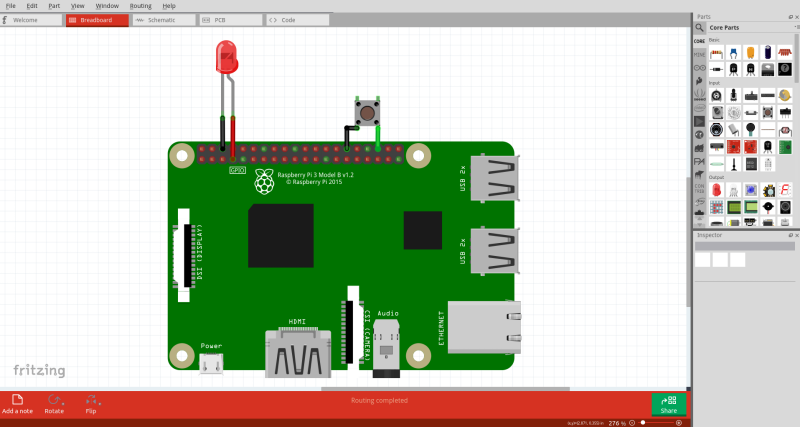
Fritzing is a tool designed to develop circuits and schematics, the connections between the components, as well as the visual part. You can download it from their official website. After you launch Fritzing, you can drag and drop components from the list on the right-top side of the screen, and make connections between them by connecting the dots on the RaspberryPi v3 with the connectors on the components. The components can be identified by their Fritzing ID. For now, the electronic components supported by the simulator are:
| Components | Fritzing ID |
|---|---|
| LEDs | <...> LED |
| Buttons | Pushbutton |
| LCDs | LCD screen |
| Raspberry Pi v3 | RaspberryPi v3 |
Do not forget, the connections between components have to be made in the Schematic tab as well as in the Breadboard tab. Also, you can set different characteristics for the components, for example, the LED color. This can be done by interqcting with the menu in the right-bottom side from the screen.
The next step is to export the required files so you can use them inside the Wyliodrin STUDIO's Raspberry Pi simulator. Once the circuit is set up, in order to use it within Wyliodrin STUDIO, you need 2 files:
- SVG file -> an interactive picture of the circuit
- XML netlist -> holds the connections list between components
To obtain these 2 files, you have to move onto the Breadboard tab and to export them by selecting File -> XML Netlist... and File -> as Image -> SVG.... If you still have questions about Fritzing, you can follow the full tutorial on How to use WyliodrinSTUDIO Simulator.
Import a circuit from Fritzing into WyliodrinSTUDIO Simulator
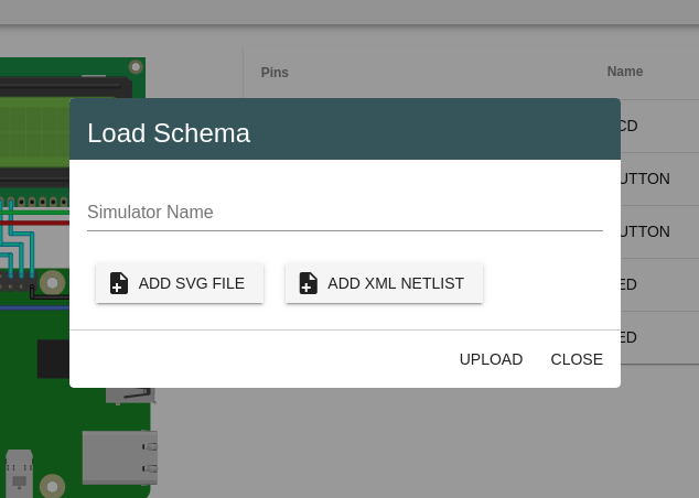
After saving the two required files, the SVG picture and the XML netlist, you have to open the list of predefined circuits. This is done by clicking the button on the left side of the screen, near the title of the circuit loaded. Then you click LOAD SCHEMA button, and a pop-up will appear.
You have to load the files required, the SVG and the XML, and give your circuit a name. If the SVG picture does not match the XML netlist, you will receive an error. Also, if there are disconnected wires in the circuit, you will see a warning. After you've done all that, you can press UPLOAD and your circuit will appear in the RASPBERRY PI SIMULATOR tab, as well as the connections table. We are working on implementing more schematics soon. They will cover a larger area of possible circuits, so you will have much less work to do. We are also working on increasing the supported components list.
Run your application
As mentioned before, the only language supported for the moment is JavaScript. In order to run an application, you can simply load your application from the PROJECTS MENU button, write the code in the APPLICATION tab, and press the RUN button. You can change the window to the RASPBERRY PI SIMULATOR tab before you press run, in order to immediatelly see the changes on the circuit. Beside the changing color of the LEDs, you can interact with the circuit by pressing the added buttons.
Examples of code
Now, let's see some source code examples for the Raspberry Pi Simulator. The first will show you how to use the GPIO pins for LEDs and buttons, while the second one will present the usage of the LCD.
LED and Button
First of all, the circuit for the code below can be found in the list of tutorials. The purpose of this circuit is to turn on and off an LED until the button is pressed. Below, as you can also see in the code, are the connections between the components and the Raspberry Pi.
| Components | Pins on RaspberryPi |
|---|---|
| LED | GPIO4 |
| Button | GPIO22 |
// Load the library onoff.Gpio
var Gpio = require("onoff").Gpio;

// Here we define the variables which control the
// pins on the RaspberryPi.
// As you can see, we have to specify the pin we
// want to control and the state of the pin.
var led = new Gpio(4, "out");
var button = new Gpio(22, "in");

// After 2 seconds, we turn the LED on, and then,
// after 2 seconds again, off again.
sleep(2000);
led.writeSync(1);
sleep(2000);
led.writeSync(0);

// We stay in this while loop until the button is
// pressed. As you can see, we read the value of
// the pin associated to the button every 1 second.
while(button.readSync() === 0) {
    sleep(1000);
}

console.log("onoff.Gpio tutorial finished!");
LCD
The purpose of this application is to show you how to work with the LCD library. The LCD component requires 8 pins to be connected: VSS, VDD, RS, E, DB4, DB5, DB6 and DB7. Bellow you will see how the pins should connect to the Raspberry Pi.
| Pins on LCD | Pins on Raspberry Pi |
|---|---|
| VSS | GND |
| VDD | 5V |
| RS | GPIO25 |
| E | GPIO2 |
| DB4 | GPIO23 |
| DB5 | GPIO17 |
| DB6 | GPIO18 |
| DB7 | GPIO22 |
// Load the library lcd
var LCD = require("lcd");

// Here we bind the variable "lcd" in order to
// control the LCD.
var lcd = new LCD({rs: 25, e: 2, data: [23, 17, 18, 22], cols: 16, rows: 2})

// Just a simple example of print
lcd.print("Hello World, from the LCD!");

sleep(2000);

// As you can see, we use this for to shift
// the text on the display one position to
// the left every second. So now, we can see
// the rest of the text displayed earlier.
for (var i = 0; i < 10; i ++) {
    sleep(1000);
    lcd.scrollDisplayLeft();
}

// After that, we just clear the LCD and unbind
// the variable.
sleep(1000);
lcd.clear();
lcd.close();

console.log("LCD tutorial finished!");
Besides these two examples, you can run a multitude of applications on the Raspberry Pi simulator. We also encourage you to build your own schematics and import them into Wyliodrin STUDIO.